


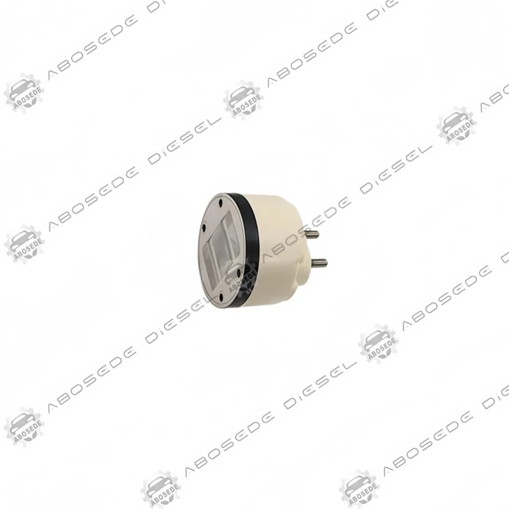

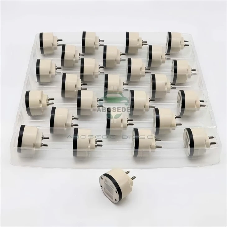
CAT C18 Solenoid Valve Assembly – Dynamic Response Calibrator For MEUI Injector Timing | 0.75Ω Primary Coil
1. Product:C18 Solenoid Valve Assembly
2. Compatible Equipment: Diesel Fuel Injection Systems
3. Manufacturer: Aftermarket OEM Replacement
4. Condition: Brand New, Fully Tested
5. Origin: ABOSEDE Diesel
6. Shipping period: 3-5 business days
7. Payment terms: T/T, Western Union, PayPal
- Fast Delievery
- Quality Assurance
- 24/7 Customer Service
Product Introduction
In the Caterpillar C18 MEUI (Mechanically actuated Electronically controlled Unit Injector) architecture, the solenoid valve assembly is not merely an actuator-it is the primary determinant of the injection pressure rise gradient. The rate at which the control valve opens determines how rapidly actuation oil pressure builds in the intensifier chamber. This pressure rise gradient (measured in MPa/ms) directly governs the fuel spray atomization quality and, subsequently, combustion efficiency. A solenoid with a delayed opening reduces this gradient, resulting in coarser fuel droplets and incomplete combustion, visible as soot accumulation on the EGR valve. The C18's larger plunger and higher fuel delivery (up to 400 mm³ per stroke) demand a solenoid that can sustain a pressure rise rate of at least 15 MPa/ms through the full stroke.
Our product is a precision-wound solenoid assembly engineered for the C18's high-flow injector platform, validated against the OEM calibration requirements for part families 10R-2772, 10R-7228, 10R-7230, and 10R-7231. The assembly is constructed with a concentrated magnetic field geometry that maximizes force output at the critical mid-stroke position (0.35mm air gap) where the control valve requires the greatest lifting force.
1. 📋 Injector Compatibility Reference – Direct from OEM Data
This solenoid assembly is dimensionally and electrically matched to the following C18 injector part numbers (serial prefixes 9NZ, 2MW, 3ZJ, 4PN, 5LJ, 6PW, 7SZ, 8KM):
| Injector Part Number | Solenoid Service Reference | Application Context |
|---|---|---|
| 253-0618 | 10R-2772 | Standard C18 ACERT (Tier 3) |
| 211-3028 | 10R-7228 | High-altitude operation (> 2,500m) |
| 291-5911 | 10R-7230 | Marine / constant-speed gen-set |
| 276-8307 | 10R-7231 | Mining / extreme vibration environments |
| 295-9085 | 10R-8988 | Remanufactured exchange core |
| 211-3026 | 10R-9787 | ADEM V ECM (late production) |
| 235-1403 | 10R-3265 | Arctic package (-40°C optimized) |
| 253-0597 | 10R-3265 | High-flow performance (650+ HP) |
| 253-0616 | 10R-3265 | Pre-DPF Tier 2 standard |
| 365-8156 | 20R-8048 | Marine with fuel temperature sensor |
| 374-0705 | 20R-8048 | Severe-duty mining spec |
| 10R-0724 | 10R-0724 | Early 9NZ series (original equipment) |
Hardware Distinction: The C18 solenoid uses a bayonet-style retaining mechanism (three-point lock ring) rather than the threaded design found on C15 solenoids. This requires a specific installation tool (Caterpillar part 9U-6196 or equivalent) for proper seating. The connector orientation is fixed at 90°; a 180° version is available for specific marine applications.

2. 📊 Dynamic Performance Parameters – The "Pressure Rise Gradient" Metric
The solenoid's dynamic performance is measured by its ability to sustain the actuation oil pressure rise gradient-a function of both magnetic force and stroke speed:
| Parameter | New Solenoid Specification | Degradation Threshold |
|---|---|---|
| Pressure Rise Gradient Achieved | 15.5 MPa/ms minimum | < 13.0 MPa/ms (poor atomization) |
| Peak Magnetic Force (0.35mm gap) | 53 N ±2% | < 47 N (incomplete lift) |
| Primary Coil Resistance @ 20°C | 0.75 Ω ±0.03Ω | > 0.82Ω (coil aging) |
| Secondary Coil Resistance @ 20°C | 1.65 Ω ±0.05Ω | > 1.75Ω (winding stress) |
| Dynamic Opening Time (0–90% lift) | 1.58 ms @ 24V | > 1.90 ms (timing retardation) |
| Stroke Completion Time (to full 0.55mm) | 1.85 ms | > 2.20 ms (incomplete opening) |
| Thermal Offset (drift @ 100°C) | < 0.02ms | > 0.06ms (material degradation) |
Graphical Abstraction – The "Pressure Rise Gradient" Curve:
Plot actuation oil pressure (Y-axis) against crankshaft angle (X-axis) for a single injection event. The solenoid's opening speed determines the slope of the initial pressure rise segment-a steeper slope indicates faster valve opening and more rapid pressure buildup. The C18's calibration assumes a minimum gradient of 15 MPa/ms to achieve the required fuel atomization. A gradient of 12 MPa/ms (degraded solenoid) produces larger droplet sizes (Sauter Mean Diameter > 25μm vs. 18μm), reducing combustion efficiency and increasing smoke opacity.
3. 🧬 Material Science – The "Focused Field" Magnetic Circuit
The C18's larger injector envelope allows for a more sophisticated magnetic circuit design than the smaller C-series solenoids:
Flux-Concentrating Core: The ferrite core incorporates a tapered profile-wider at the base and narrower at the pole face-which concentrates the magnetic flux at the air gap, increasing the force output by approximately 12% without increasing current draw.
Low-Hysteresis Laminations: The core laminations are made from 4% silicon-iron alloy with a low coercivity (< 100 A/m), which reduces the energy loss during each magnetic cycle. This translates to cooler operation: a temperature rise of only 35°C above ambient at continuous hold current (vs. 50°C for conventional steel cores).
Copper Cross-Section Optimization: The pull-in winding uses a rectangular copper conductor (rather than round wire), which provides 15% more cross-sectional area in the same bobbin space. This reduces resistance and allows higher peak current for faster pull-in.
Visual Innovation – Polarity Marking:
The housing is laser-etched with a "+" symbol adjacent to the pull-in terminal and a "-" symbol adjacent to the hold terminal. While the solenoid is not polarity-sensitive for operation, these markings assist in confirming proper ECM driver connections during diagnostics.
4. 🔧 Installation Protocol – The "Bayonet Lock" Method
Step 1 – Clean and Inspect: Verify that the injector's control valve bore is free from debris. Use a lint-free cloth and isopropyl alcohol.
Step 2 – O-Ring Installation: Lubricate the supplied Viton O-ring with clean engine oil and install it in the groove on the solenoid's base.
Step 3 – Bayonet Seating: Align the three lock pins on the solenoid with the slots on the injector body. Press downward firmly and rotate clockwise 30° until you hear a distinct click. The click indicates the lock ring has engaged.
Step 4 – Torque Check: Use a crows-foot attachment to torque the lock ring to 4.5 N·m (the bayonet design requires higher torque than threaded designs).
Step 5 – Connector Mating: Push the harness connector until the latch engages. Verify that the connector's backshell is fully seated against the solenoid housing-a 1mm gap indicates incomplete connection.
Step 6 – Calibration: Perform the "Injector Solenoid Learn" routine using Cat ET. This procedure is mandatory for the ADEM V ECM to establish the new solenoid's response profile.
📋 FAQ – Specific to C18 Applications
Q1: I've replaced the solenoid but still get a "359" fault code (Response Time Fault). What else could be wrong?
The ECM measures response time as the interval between the pull-in command and the observed current drop (caused by the armature hitting the stop). If the connector terminals have high resistance, the ECM sees a slower current rise and logs a fault. Clean the terminals with contact cleaner and apply dielectric grease. Also verify that the battery voltage is at least 23V during operation.
Q2: Can this solenoid be rebuilt, or is replacement the only option?
The solenoid is a sealed, non-serviceable unit. The winding insulation degrades over time from thermal cycling, and the armature guide wears, increasing stiction. We do not recommend rebuilding-the cost of replacement parts and labor often exceeds the cost of a new unit.
Q3: Our C18 is used in a mining haul truck with severe vibration. Will the bayonet lock loosen over time?
The bayonet lock includes a spring-loaded detent that prevents rotation under vibration. We have validated this design to 20 G peak vibration (10–500 Hz) with no measurable rotation. We recommend checking the lock ring torque at the 500-hour service interval as a best practice.
Q4: How does this solenoid perform with biodiesel blends (B20 and above)?
The solenoid's electrical and magnetic performance is unaffected by fuel composition. However, biodiesel has a higher viscosity and density, which increases the hydraulic resistance in the spill valve. This places a slightly higher mechanical load on the solenoid. We recommend decreasing the replacement interval from 8,000 to 6,000 hours when running B20 or higher.
Q5: I have a 295-9085 reman injector with a different solenoid reference (10R-8988). Will this solenoid fit?
Yes, the mounting interface is identical. The 10R-8988 reference is for a complete solenoid assembly that includes mounting hardware. Our product is a complete assembly that directly replaces the 10R-8988.
Q6: There's a "coil resistance" specification in the manual-should I match this exactly?
The specification is 0.75Ω ±0.04Ω. A deviation of ±0.05Ω (to 0.80Ω or 0.70Ω) is still within acceptable limits and will not significantly affect performance. However, a resistance of > 0.85Ω indicates corrosion or winding damage-replace the solenoid.


Flexible Payment Methods for Your Convenience
To make your purchasing experience smooth and easy, we offer a variety of secure payment options:

Bank Transfer
Supports multiple currenciesand bank payment methods.

Western Union
Quick and global money transfers.

PayPal
Safe and convenient online payment.

Alibaba
Enjoy extra protection with trusted Alibaba transactions.
We're here to make your order process worry-free - choose the payment method that works best for you!
Shipping Made Simple

Customer reviews

Hot Tags: cat c18 solenoid valve assembly – dynamic response calibrator for meui injector timing | 0.75ω primary coil, China cat c18 solenoid valve assembly – dynamic response calibrator for meui injector timing | 0.75ω primary coil manufacturers, suppliers, factory, cat valve
You Might Also Like
-

CAT C10 Solenoid Valve Assembly | Electronic Control...
-

CAT C11 Injector Solenoid Valve – The Time-Transduce...
-

CAT C13 Solenoid Valve Assembly – Hydraulic Amplific...
-

CAT C15 Solenoid Valve Assembly – Precision Winding ...
-

Supply‑Side Discipline: The CAT C7 Fuel Inlet Check ...
-
Common Rail Injector Control Valve Cat C13 C15 C18 E...
