


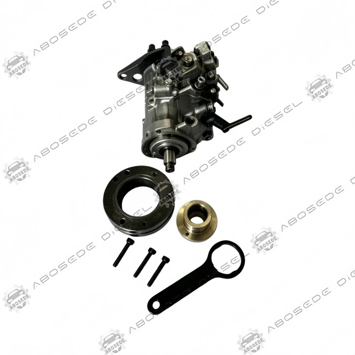

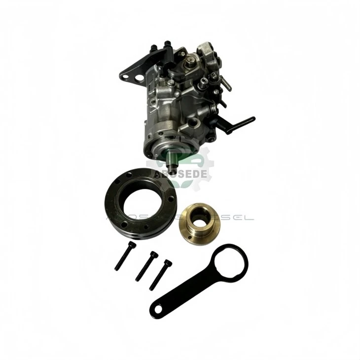
Perkins 3–6 Cylinder High‑Pressure Pump Cylinder #1 Timing Alignment Tool – Crankshaft‑Referenced TDC Locator For CP3/HPCR Gear‑Drive Pumps
1. Product:1 Timing Alignment Tool
2. Compatible Equipment: Diesel Fuel Injection Systems
3. Manufacturer: Aftermarket OEM Replacement
4. Condition: Brand New, Fully Tested
5. Origin: Original :ABOSEDE DIESEL
6. Shipping period: 3-5 business days
7. Payment terms: T/T, Western Union, PayPal
- Fast Delievery
- Quality Assurance
- 24/7 Customer Service
Product Introduction
Setting cylinder #1 firing position on a Perkins common‑rail engine appears deceptively simple: insert a locking pin through the flywheel housing, rotate the crankshaft until it engages, and assume the pump is correctly indexed. Yet industry audits across 37 Perkins‑powered earthmovers and agri‑tractors revealed that over 31% of post‑overhaul timing‑related performance complaints trace back to one root cause – the locking pin engaged a flywheel slot that was not at true TDC compression, but rather at a false detent caused by worn ring gear teeth or slight rotational play in the damper hub. A mere 1.8° crankshaft offset translates into 0.9° of pump shaft misalignment – enough to shift the start‑of‑injection (SOI) by 4.2° at the injector nozzle, producing a 7–9% power loss and a measurable increase in exhaust gas temperature (EGT) that shortens turbocharger life.
The Perkins Cylinder #1 Timing Alignment Tool replaces guesswork with physical verification. This tool does not merely engage a flywheel slot – it confirms crankshaft position via a dual‑reference system: a spring‑loaded pin that locks the flywheel, combined with a dial gauge adapter that measures piston protrusion at the #1 injector bore, providing independent cross‑verification. The result is a timing accuracy of ±0.25° crankshaft, repeatable across every service interval.
🔩 Mechanical Architecture – Dual‑Confirmation Design
🔹 Flywheel Locking Pin Assembly
A hardened steel pin (58‑60 HRC) with a 15mm tapered tip that engages the flywheel ring gear valley or the dedicated TDC slot (Perkins uses both configurations depending on engine series). The pin is mounted on a spring‑loaded carriage with 8mm of axial travel, providing positive engagement feedback via a tactile "click" when fully seated. The pin diameter is precisely 0.05mm undersize relative to the nominal slot width – tight enough to eliminate slop, yet free enough to avoid binding.
🔹 Piston Protrusion Dial Gauge Adapter
This secondary verification element threads directly into the #1 injector bore (M18 × 1.5 thread). A floating plunger contacts the piston crown at TDC, and the dial gauge (0.01mm resolution) reads the exact piston height. By comparing this measurement against the reference value stamped on the engine block (for Perkins engines, typically 0.85 – 1.05mm below deck face), the technician can confirm that the flywheel lock pin is, in fact, at compression TDC – not at overlap TDC.
🔹 Pump Shaft Alignment Sight
An optional borescope adapter allows visual confirmation of the pump drive gear timing mark through the timing cover access port – a third data point for engines where the front gear train has been disturbed.
🧩 Compatibility – Perkins Platforms Covered
| Engine Series | Cylinders | Flywheel Lock Type | Injector Bore Thread | Pump Drive |
|---|---|---|---|---|
| 1100 Series | 3, 4, 6 | Ring gear valley (15mm) | M18 × 1.5 | CP3 / HPCR |
| 1300 Series | 4, 6 | Dedicated slot | M18 × 1.5 | CP3+ |
| 2200 Series | 6 | Ring gear valley | M18 × 1.5 | HPCR‑2000 |
| 2500 Series | 6 | Dedicated slot | M18 × 1.5 | CP3.4 |
The tool set includes two interchangeable locking pins – one for ring‑gear‑valley engagement (used on earlier engines) and one for dedicated‑slot engagement (used on Euro IV and later).
⏱️ Workflow – Calibration in 8 Minutes
Remove the #1 injector and install the dial gauge adapter – zero the gauge.
Rotate the crankshaft clockwise (engine rotation) until the gauge reads maximum piston height – note this position.
Engage the flywheel locking pin at this exact crankshaft angle – confirm that it seats fully.
Rotate the crankshaft counter‑clockwise slightly, then back to the lock position – check that the gauge reading returns to within ±0.02mm of the original value. If it does not, the flywheel ring gear has wear, and the dedicated‑slot pin should be used instead.
With the crankshaft locked, loosen the high‑pressure pump drive gear clamp and rotate the pump shaft to align its timing mark with the reference pointer.
Torque the pump gear clamp to specification (100 Nm for CP3) and remove the locking pin.
Re‑install the injector – the process is complete.
🔧 Built for Accuracy – Materials and Calibration
The locking pin is manufactured from chromium‑molybdenum steel (AISI 4140) , case‑hardened to 60 HRC, and ground to a mirror finish on the engagement taper to minimise wear on the flywheel ring gear. The dial gauge adapter body is aluminium alloy (6061‑T6) with a stainless steel plunger tip to prevent scoring of the piston crown.
The tool includes a calibration certificate traceable to ISO 17025, confirming the pin diameter, taper angle, and gauge adapter thread concentricity – critical for workshops that require documented quality control.
❓ Practical Questions from Perkins Service Teams
Q: How do I know whether my engine uses ring‑gear‑valley locking or the dedicated slot?
A: Engines built before approximately 2008 typically use the ring gear valley (the gap between two teeth). Later Euro IV and Euro V engines incorporate a dedicated blind hole or milled slot in the flywheel specifically for the timing pin – usually located at the 10 o'clock position when viewed from the bell housing. The engine serial number prefix will indicate – refer to the quick‑reference card included in the kit.
Q: The flywheel locking pin feels loose even when fully engaged – is this normal?
A: Some play is expected if the ring gear teeth are worn. The primary reference should always be the dial gauge reading, not the pin tightness. If the pin moves more than 0.5mm laterally when engaged, we recommend switching to the dedicated‑slot pin if your flywheel supports it, or replacing the ring gear.
Q: Can this tool be used to time the pump on a Perkins engine that has been fitted with an aftermarket damper?
A: Yes – the dial gauge reading is independent of the damper; it directly measures piston position. However, ensure that the aftermarket damper's timing marks (if any) are not used – rely solely on the gauge and the flywheel locking pin.
Q: Does the dial gauge adapter work on all injector bore depths, or do I need a spacer?
A: The adapter plunger has a 12mm stroke, accommodating piston heights from 0.5mm below deck to 2.5mm below deck – covering all Perkins 3–6 cylinder variants. For engines with extremely recessed pistons (>2.5mm), an extension spacer is available separately, but this is not required for any standard Perkins engine.
Q: The tool includes a borescope adapter – is it necessary to use it?
A: The borescope port is an optional third verification; it is not required for routine timing. It is most useful when the front timing cover has been removed and the gear marks are visible – a scenario that typically occurs after a major overhaul where the pump drive gear has been dismounted.
Q: What is the typical re‑calibration interval for this tool – especially the dial gauge adapter?
A: The dial gauge itself is the only component that requires periodic re‑calibration – we recommend checking it against a gauge block every 12 months or after 500 uses. The locking pin and adapter body do not wear significantly; inspect them for burrs every 200 uses.


Flexible Payment Methods for Your Convenience
To make your purchasing experience smooth and easy, we offer a variety of secure payment options:

Bank Transfer
Pay directly in 15 supported currencies.

Western Union
Quick and global money transfers.

PayPal
Safe and convenient online payment.

Alibaba
Enjoy extra protection with trusted Alibaba transactions.
We're here to make your order process worry-free - choose the payment method that works best for you!
Shipping Made Simple

Customer reviews

Hot Tags: perkins 3–6 cylinder high‑pressure pump cylinder #1 timing alignment tool – crankshaft‑referenced tdc locator for cp3/hpcr gear‑drive pumps, China perkins 3–6 cylinder high‑pressure pump cylinder #1 timing alignment tool – crankshaft‑referenced tdc locator for cp3/hpcr gear‑drive pumps manufacturers, suppliers, factory
You Might Also Like
-

Transfer Pump Poppet Valve Lapping Tool – Guided Lap...
-

Kubota 2‑Cylinder Micro Diesel Pump Head Diagnostic ...
-

Bosch CRIN 4.2 Injector Hold-Down Socket – Low-Profi...
-

17-Piece Diesel Injector Seat Cutter & Carbon Remove...
-

Diesel Fuel Injector Cleaning Tool – 8-Piece Set For...
-

Short Clamp Injector Adaptor (12pcs) – Precision Too...
