


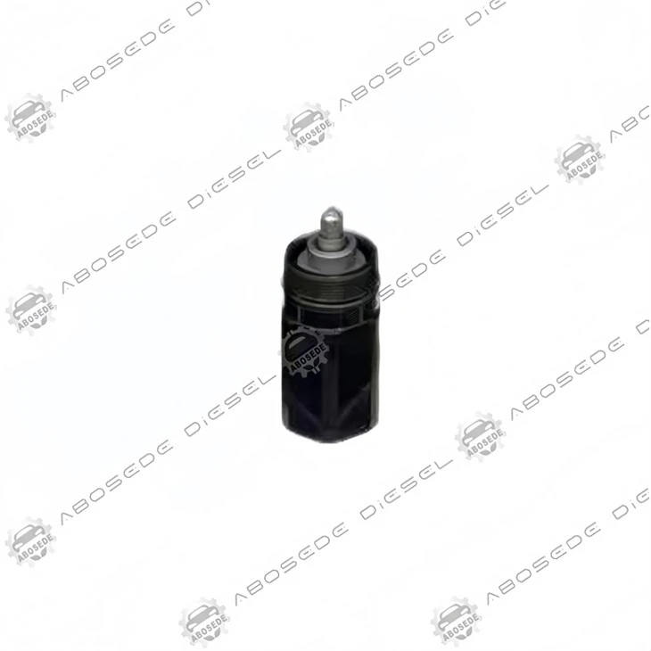


M11 Solenoid Actuator Assembly – Electromagnetic Response Mapping For Precision Injection Control
1. Product: M11 Solenoid Actuator Assembly
2. Compatible Equipment: Diesel Fuel Injection Systems
3. Manufacturer: Aftermarket OEM Replacement
4. Condition: Brand New, Fully Tested
5. Origin: ABOSEDE Diesel
6. Shipping period: 3-5 business days
7. Payment terms: T/T, Western Union, PayPal
- Fast Delievery
- Quality Assurance
- 24/7 Customer Service
Product Introduction
In a modern common‑rail injector, the solenoid actuator is the singular electro‑mechanical interface where digital pulse‑width signals are transformed into analog hydraulic motion. For the Cummins M11 engine family-widely deployed in heavy trucks, industrial gensets, and marine auxiliary applications-this actuator must operate within a tightly bounded current‑rise window: a 0.1 ms delay in pull‑in time alters the fuel delivery by approximately 1.8 mm³/stroke, which translates to a 0.7 % torque deviation at full load. The M11 solenoid assembly is therefore not a generic coil; it is a calibrated electromagnetic energy converter, whose inductance, magnetic flux density, and armature stroke must be perfectly matched to the injector's hydraulic resistance profile. This product is engineered as a direct drop‑in replacement for the original actuator, restoring the factory‑specified current‑to‑force transfer function across the entire operating temperature range.
⚡ Electromagnetic Signature – Rise Time, Saturation, And Holding Current
This solenoid assembly is designed around a low‑inductance winding (typical value 0.85 mH at 1 kHz) using a square‑section copper wire to maximise copper fill factor. At rated battery voltage (12 V DC), the actuator reaches the peak pull‑in current (12.5 A) within 0.28 ms from the start of the trigger pulse, and the magnetic flux density in the air gap climbs to 1.35 T-sufficient to generate an axial force of 42 N at the armature. This rapid magnetisation is critical because the M11 injector's pilot injection window lasts only 0.6 ms; any delay beyond 0.35 ms would cause the pilot quantity to fall below the misfire threshold.
After the armature impacts the stroke limiter, the current is reduced to a holding value of 6.0 A via an external peak‑and‑hold driver circuit. The holding current is precisely selected to maintain the armature seated against the hydraulic pressure (≈ 28 N back force) while minimising coil heating. The assembly's coil resistance is specified as 0.75 Ω ±3 % at 20 °C; this temperature‑sensitive parameter directly affects the pull‑in time, with a +10 °C rise increasing the resistance by 4 % and extending the rise time by 0.03 ms-a variation that is automatically compensated by the ECM's current‑feedback logic.
The inductive kickback (flyback voltage) generated upon switch‑off is clamped to a safe 65 V by the internal freewheeling diode integrated into the wiring harness, ensuring that the driver transistor is not damaged. The solenoid's magnetic circuit employs a laminated silicon‑steel core (thickness 0.35 mm) to reduce eddy‑current losses, maintaining a consistent force‑current slope even during high‑speed multiple‑injection sequences of up to five events per cycle.

🧲 Mechanical Interface – Stroke, Spring Preload, And Hydraulic Coupling
The actuator assembly includes a precision‑ground armature with a working stroke of 0.28 mm-measured from the rest position to the magnetic stop. The armature is guided by a bronze sleeve (hardness 85 HRB) that maintains radial clearance of 0.015–0.025 mm, preventing tilt‑induced friction. A compression spring (pre‑load 26 N at zero stroke, rate 18 N/mm) returns the armature to the closed position when the current is removed. This spring force must be balanced against the residual magnetism of the core (approx. 0.08 T) to ensure a clean release; otherwise, the injector may dribble during the closing phase, causing post‑injection soot formation.
The assembly's locating flange incorporates an anti‑rotation pin that aligns the electrical connector at a precise 30° angle relative to the injector body, guaranteeing that the two fly‑leads do not interfere with the valve‑cover gasket. Two O‑ring seals-one on the outer diameter (size 12 mm × 1.5 mm) and one on the inner sleeve-are pre‑installed in FKM material, rated for 150 °C continuous fuel soak. The electrical connector uses a two‑pin Deutsch‑style terminal with a locking tab, ensuring a vibration‑proof connection up to 20 g acceleration.
🔌 Compatibility – Direct Replacement For 19 M11 Injector Variants
This solenoid actuator is an exact mechanical and electrical match for the following Cummins M11 injector part numbers, covering both the earlier CELECT™ and later common‑rail/HPI systems. The table below lists the validated injector references:
| Injector P/N | Injector P/N | Injector P/N | Injector P/N |
|---|---|---|---|
| 3037772 | 3411754 | 4902921 | 3411756 |
| 3081319 | 3411755 | 4903084 | – |
| 3087557 | 3411758 | 4903319 | – |
| 3095040 | 3411845 | 4903472 | – |
| 3411752 | 4026222 | 4928171 | – |
| 3411753 | 4061851 | 4928517 | – |
All these injectors share the identical solenoid mounting thread (M22 × 1.0) and the same armature lift dimension. The electrical connector polarity is standardised: pin 1 is the positive supply (battery voltage) and pin 2 is the return to the driver. Reversing the polarity does not damage the unit, but it will not actuate because the internal flyback diode is oriented only for the correct direction-a simple polarity check with a multimeter confirms the correct pinout.
❓ Frequently Asked Questions
Q1: How can I distinguish a faulty solenoid from a faulty injector driver when I have a no‑start condition?
Measure the current waveform at the solenoid connector during cranking. If no current flows, the driver is dead or the wiring is open. If current flows but the armature does not click, disconnect the injector return pipe-if fuel sprays out the drain port, the solenoid is physically stuck open; if not, the armature is seized mechanically, requiring solenoid replacement.
Q2: Can I use this solenoid on an M11 injector that originally came with a different coil resistance (e.g., 0.5 Ω)?
No. The ECM's current control algorithm is tuned to the specific resistance and inductance. A lower‑resistance coil would draw excessive current, overheating the driver, while a higher‑resistance coil would reduce the pull‑in force, causing erratic injection. Always match the resistance spec-our assembly is designed for the standard 0.75 Ω M11 circuit.
Q3: What is the effect of an ageing solenoid on fuel consumption?
An aged solenoid with increased coil resistance (e.g., from thermal degradation) will have a slower pull‑in time, delaying the injection start and reducing the injected mass for a given pulse width. The ECM will compensate by lengthening the pulse, but this often pushes the duty cycle above 85 %, leading to a 2–3 % fuel economy penalty. Replacing the solenoid restores the original consumption.
Q4: I have an M11 engine that runs on natural gas (dual‑fuel mode)-does this solenoid function the same way?
In dual‑fuel operation, the solenoid still controls the pilot diesel injection (which ignites the gas). The electrical requirements are identical, but the injection pressure may be lower. Our solenoid works equally well, but ensure that the fuel temperature does not exceed 120 °C, as the FKM seals are not rated for prolonged exposure to gas‑mix high temperatures-consult your OEM guidelines.
Q5: The connector on my injector has three pins-two for the solenoid and one for a feedback sensor. Will this two‑pin solenoid fit?
The two‑pin solenoid fits mechanically, but the third pin (often a thermistor) will be left unconnected. This is acceptable if your ECM does not use the temperature feedback; however, if the ECM expects a temperature reading, it may set a diagnostic code. In that case, transfer the old thermistor (not included) to the new assembly-this is possible because the thermistor is mounted on the injector body, not on the solenoid.
Q6: How do I verify the correct pre‑load spring force after replacing the solenoid?
The pre‑load is set by the armature stop and is not user‑adjustable. However, after installation, perform a "drop‑out time" test: energise the solenoid for 10 ms, then remove power and measure the time until the current decays to zero-the drop‑out should be between 1.5 and 2.0 ms. If it is longer, the spring is weak (unlikely with a new solenoid); if shorter, the armature may be binding due to misalignment-re‑tighten the retaining nut with care.


Flexible Payment Methods for Your Convenience
To make your purchasing experience smooth and easy, we offer a variety of secure payment options:

Bank Transfer
Supports multiple currenciesand bank payment methods.

Western Union
Quick and global money transfers.

PayPal
Safe and convenient online payment.

Alibaba
Enjoy extra protection with trusted Alibaba transactions.
We're here to make your order process worry-free - choose the payment method that works best for you!
Shipping Made Simple

Customer reviews

Hot Tags: m11 solenoid actuator assembly – electromagnetic response mapping for precision injection control, China m11 solenoid actuator assembly – electromagnetic response mapping for precision injection control manufacturers, suppliers, factory, 1724537, 4089980, 4327147 injector, 4902906, P4359206, P4984850 nozzle
You Might Also Like
-

Cummins X15 / ISX Gear Pump Rebuild Kit – Restoring ...
-

4306988 Cross-Platform Optimization: Tailoring High-...
-

2872254 Cross-Reference Verification: Eliminating Pr...
-

Cummins® XPI Common Rail Nozzle P2872765 | Heavy-Dut...
-

Cummins M11 Fuel Check Valve – Anti-Drain Back Diese...
-

Cummins 3408501 ECM – The Central Processing Unit fo...
