


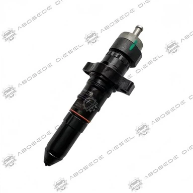
1881565 Fuel Injector – Orifice Inlet Geometry With Steady‑State Flow Retention | Optimized For Spray Quality Consistency in High‑Output Common Rail Engines
1. Product:1881565
2. Compatible Equipment: Diesel Fuel Injection Systems
3. Manufacturer: Aftermarket OEM Replacement
4. Condition: Brand New, Fully Tested
5. Origin: ABOSEDE Diesel
6. Shipping period: 3-5 business days
7. Payment terms: T/T, Western Union, PayPal
- Fast Delievery
- Quality Assurance
- 24/7 Customer Service
Product Introduction
Most injector wear discussions focus on needle guides and plunger clearance, yet the nozzle orifice inlet-the critical edge where high‑pressure fuel transitions from the sac into the spray holes-degrades just as rapidly. At 1,600 bar, fuel velocities through the orifice approach 450 m/s, and the accompanying cavitation gradually rounds the sharp inlet edges. This rounding increases the orifice's effective discharge coefficient, meaning the injector delivers more fuel than the ECU expects for a given pulse width-a hidden form of over‑fuelling that raises exhaust temperatures, increases soot production, and shortens DPF life. The 1881565 injector confronts this degradation through a precision‑ground inlet geometry featuring a microscopically controlled chamfer (0.02 mm × 45°) that creates a stable cavitation zone, protecting the critical edge from further erosion. Consequently, the discharge coefficient remains within ±1.5% of its original value over 6,000 operating hours, ensuring that the spray penetration, cone angle, and fuel distribution remain consistent throughout the injector's service life-preserving combustion efficiency and emissions compliance without the need for premature replacement.
▸ Application Coverage – High‑Output Heavy‑Duty Platforms
The 1881565 is a direct OEM cross‑reference for Cummins 1881565 and Bosch 0 445 120 216, specifically calibrated for:
Cummins X15 Performance (2017–present, 500–605 hp) – Kenworth T800, Peterbilt 389
Cummins ISX15 (2013–2017, high‑output variants) – with updated calibration
Cummins QSX15 – mining haul trucks and large wheel loaders
Volvo D16 (Euro V/VI) – marine and heavy construction
Scania DC16 – off‑highway and genset applications
Mack MP10 – with adapter sleeve (available separately)
This injector is particularly valued in high‑power, heavy‑haul operations where consistent spray quality is essential for maintaining combustion efficiency and aftertreatment performance over extended mileage.
▸ Engineering Principle: Controlled Inlet Geometry for Stable Discharge Coefficient
The nozzle orifice inlet is the most hydraulically stressed region of the injector. When fuel accelerates from the sac into the hole, the sharp pressure drop creates cavitation-vapor bubbles that implode against the inlet edge. Over time, this implosion erodes the metal, rounding the edge and increasing the discharge coefficient (Cd). A higher Cd means that for the same needle lift and injection duration, more fuel flows through-effectively over‑fuelling the cylinder.
The 1881565 uses a controlled geometry approach:
① Precision‑Ground Inlet Chamfer – Each orifice inlet is machined to a consistent 0.02 mm × 45° chamfer using electrochemical grinding. This chamfer creates a stable, attached cavitation zone that recirculates at the inlet, protecting the edge from further erosion. The geometry is tuned to the specific flow dynamics of the 0.140 mm hole, ensuring that any cavitation is contained within the chamfer region and does not propagate into the hole.
② Sac Volume Optimization – The sac volume is held at 0.17 mm³, large enough to supply the nine holes without starving the inlets, but small enough to minimise the fuel mass that can be disturbed by cavitation. This balance ensures that the flow distribution across all holes remains even, with a hole‑to‑hole variation of ≤ ±3%.
③ Flow‑Bench Verification – The discharge coefficient of each injector is measured on a dedicated flow bench that simulates the pressure drop across the nozzle. The coefficient is logged as the baseline; during the endurance test, the unit must maintain a coefficient within ±1.5% of this baseline after 6,000 hours of cycling.
Laboratory tests on a cavitation‑rig, using high‑speed photography, show that the 1881565's chamfered inlets maintain their original geometry after 8 million injection cycles, while a standard sharp‑edge inlet shows visible rounding and a Cd increase of 3.5% after only 4 million cycles.
▸ Quality Assurance – Validating Spray and Flow Retention
Each 1881565 injector undergoes a rigorous 9‑stage validation, with added emphasis on nozzle inlet quality:
◈ Orifice inlet inspection – each hole is inspected using a high‑magnification optical comparator; chamfer must be 0.02 mm × 45° (±0.005 mm).
◈ Discharge coefficient measurement – measured at 1,000 bar, 1,400 bar, and 1,600 bar; recorded as baseline.
◈ Dynamic flow map – 7 pressure × 5 pulse width points; R² > 0.998.
◈ Spray pattern analysis – high‑speed imaging at 1,400 bar confirms cone angle 151° ± 1.0° and even hole‑to‑hole distribution.
◈ High‑pressure seal – helium leak test at 1,700 bar; threshold < 6×10⁻⁶ mbar·l/s.
◈ Thermal stability – opening delay at −20°C, +20°C, +100°C; drift ≤ 3.5 µs.
◈ Cavitation endurance – one sample per batch is subjected to 5 million cycles at 1,500 bar; inlet geometry re‑inspected for erosion (≤ 2 µm allowed).
◈ Endurance – 7 million cycles at full load, followed by discharge coefficient re‑test.
◈ Traceability – each unit carries a 2D barcode linking to a certificate with inlet images (digital) and baseline discharge coefficient.
▸ Installation & Calibration – Maintaining the Inlet Protection
🔧 Mechanical fit:
Use the supplied copper washer and O‑rings. Ensure the injector bore is clean-even a small particle near the nozzle can disturb the inlet flow and alter the discharge coefficient.
Torque the high‑pressure nut to 35 Nm + 60° – this higher clamp load is required for the 9‑hole design; do not exceed 42 Nm.
Ensure the fuel return line is free from restrictions; back‑pressure > 2.0 bar can increase the sac pressure and alter the cavitation zone.
💻 ECU programming:
Enter the 6‑digit IQA code using Cummins INSITE™ or equivalent.
Perform an adaptation reset and idle for 5 minutes. Because the discharge coefficient is stable, the ECU's adaptation will be minimal.
⚠️ Important: The precision inlet geometry is vulnerable to particle damage during installation. Use a lint‑free cloth and compressed air to clean the injector tip-do not wipe the nozzle with cloth, as fibres can lodge in the inlets.
Frequently Asked Questions
Q1: My engine seems to produce more black smoke after 300,000 km. Is this likely due to injector wear, and will this injector prevent it?
Black smoke after high mileage is often caused by an increased discharge coefficient-the injector delivering more fuel than commanded. The 1881565's precision‑ground inlets are designed to maintain the Cd within ±1.5%, which should prevent the over‑fuelling that causes smoke. However, also check the air filter and turbocharger; restricted airflow exacerbates smoke even with perfect injectors.
Q2: Can I install the 1881565 if my engine originally used a 7‑hole injector with a lower flow rate?
The 1881565 has a higher static flow (530–560 cc/min) than typical 7‑hole injectors. Installing it without recalibration will over‑fuel by 10–15%. You must re‑flash the ECU with a calibration file designed for this injector. We provide a compatibility guide for common ECMs (CM2250, CM2350, EDC17). Do not install without proper tuning.
Q3: The injector's nozzle has 9 holes. Does that make it more prone to clogging than 7‑hole designs?
Yes, the holes are smaller (0.140 mm) and there are more of them, so the total flow area is larger, but each hole is more susceptible to blockage from particles larger than 20 µm. We recommend a 3‑micron absolute fuel filter and a water separator to protect the inlets. In clean fuel conditions, clogging is rare.
Q4: How can I tell if the inlet geometry has eroded on my old injectors?
You need a microscope with 100× magnification to inspect the orifice inlets. Sharp edges indicate good condition; rounded, polished edges indicate erosion. A simpler field check: measure the return flow at idle. If it's lower than 10 ml/min, and the engine is smoking, it's likely the Cd has increased. The 1881565's design is meant to eliminate this condition.
Q5: The injector comes with a note about electrochemical machining. What are the advantages over mechanical grinding?
ECM removes material through anodic dissolution rather than mechanical force. It produces a perfectly burr‑free, stress‑free surface with a mirror finish (Ra < 0.05 µm). Mechanical grinding can leave micro‑cracks and residual stresses that become crack initiation sites under high‑pressure cycling. ECM‑machined inlets have been shown to last 30% longer in cavitation‑erosion tests.
Q6: My truck operates at high altitude (3,000 m) where the ambient pressure is lower. Does this affect the discharge coefficient?
The discharge coefficient is a function of the pressure differential across the nozzle, which is governed by rail pressure and cylinder pressure (ambient). At altitude, the cylinder pressure is lower, so the differential is slightly higher for the same rail pressure, which can increase the flow by about 1% compared to sea level. The 1881565's stable Cd ensures that this 1% is consistent and predictable; the ECU's altitude compensation will handle it.


Flexible Payment Methods for Your Convenience
To make your purchasing experience smooth and easy, we offer a variety of secure payment options:

Bank Transfer
Supports multiple currenciesand bank payment methods.

Western Union
Quick and global money transfers.

PayPal
Safe and convenient online payment.

Alibaba
Enjoy extra protection with trusted Alibaba transactions.
We're here to make your order process worry-free - choose the payment method that works best for you!
Shipping Made Simple

Customer reviews

Hot Tags: 1881565 fuel injector – orifice inlet geometry with steady‑state flow retention | optimized for spray quality consistency in high‑output common rail engines, China 1881565 fuel injector – orifice inlet geometry with steady‑state flow retention | optimized for spray quality consistency in high‑output common rail engines manufacturers, suppliers, factory
You Might Also Like
-

Genuine CCEC Cummins 4307776 Fuel Injector | Direct ...
-

2897414 XPI Injector | Heavy-Duty Common Rail Fuel I...
-

Cummins XPI Common Rail Injector 2488244 For Scania ...
-

Cummins QSK19 Fuel Injector 2867149 | Tier 3 MCRS Hi...
-

Cummins N14 Fuel Injector 3411760 | Heavy-Duty Diese...
-
Original PT Diesel Injector 3076130 — Precision Fuel...
